PID Motor Control
Closed-loop PID motor controller on STM32 Nucleo-F411RE with real-time IMU feedback. Live tuning happens over UART, with step response capture to CSV for plotting.
Hardware
| Component | Part | Interface |
|---|---|---|
| MCU | STM32 Nucleo-F411RE | - |
| Motor Driver | TB6612FNG | GPIO + PWM |
| IMU | MPU-6050 (6-axis) | I2C1 @ 400 kHz |
| Display | SSD1306 0.96” OLED | I2C1 @ 0x3C |
| Motor | 130-type DC | via TB6612FNG |
| Debug | ST-Link VCP (USART2) | 115200 baud |
Wiring
STM32 Nucleo-F411RE          TB6612FNG
  PA6 (TIM3_CH1) ----------> PWMA
  PA5 ----------------------> AIN1
  PA8 ----------------------> AIN2
  PA9 ----------------------> STBY
  3.3V ---------------------> VCC
  GND ----------------------> GND
  external 5-12V -----------> VM

STM32                         MPU-6050
  PB8 (I2C1_SCL) --+-------> SCL
  PB9 (I2C1_SDA) --+-------> SDA
  3.3V -------[4.7K]--+      VCC
              [4.7K]--+      GND
  pull-ups to 3.3V           AD0 -> GND, address 0x68

STM32                         SSD1306 OLED
  PB8 (shared SCL) ---------> SCL
  PB9 (shared SDA) ---------> SDA
  3.3V ---------------------> VCC
  GND ----------------------> GND

USART2 on PA2/PA3 is routed through the ST-Link virtual COM port.
Architecture
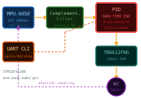
TIM3_CH1 (20 kHz PWM) --> TB6612FNG --> DC Motor
                                          |
MPU-6050 (I2C, 14-byte burst read) <-----+
    |                                  (physical coupling)
    v
Complementary Filter (alpha=0.98)
    |
    v
PID Controller (1 kHz, TIM2 ISR)
    |  - Derivative on measurement
    |  - Low-pass filter on D term (N=10)
    |  - Integral clamping anti-windup
    v
Motor effort (-1.0 to +1.0) --> sign-magnitude drive

Main loop:
  - UART CLI for Kp, Ki, Kd, setpoint, and step response commands
  - OLED display for gains, setpoint, error, and output bar
  - CSV step response stream for offline plotting
Control Design
The PID loop runs at 1 kHz in TIM2’s update ISR. Three techniques keep the output clean:
Derivative on measurement. The D term differentiates the process variable, not the error signal. This eliminates the derivative kick that occurs when the setpoint changes abruptly.
Low-pass filter on D term. A first-order filter with N=10 smooths high-frequency noise from the IMU without adding significant phase lag at the control bandwidth.
Integral anti-windup. The integrator is clamped to the output range. When the motor saturates, the integrator stops accumulating, preventing overshoot on recovery.
UART CLI
The main loop runs a serial command interface for live tuning:
| Command | Description |
|---|---|
kp <value> |
Set proportional gain |
ki <value> |
Set integral gain |
kd <value> |
Set derivative gain |
sp <angle> |
Set target angle |
step <angle> |
Step to angle and stream 2 seconds of CSV |
reset |
Zero the PID integrator |
status |
Print current gains, setpoint, error |
help |
Print command list |
Step response data streams as CSV over UART for offline plotting with scripts/plot_step_response.py.
Build
Requires arm-none-eabi-gcc and CMake.
mkdir build && cd build
cmake -DCMAKE_BUILD_TYPE=Debug ..
make
Flash via ST-Link:
make flash
# or:
st-flash write pid-motor-control.bin 0x08000000
Connect a serial terminal at 115200 baud:
screen /dev/tty.usbmodem* 115200
Tuning Procedure
- Start with
kp 1.0,ki 0,kd 0. - Increase Kp until the system oscillates, then back off 20-30%.
- Add Ki from a small value until steady-state error is eliminated.
- Add Kd to dampen oscillations.
- Use
step <angle>to capture response data for plotting.
Milestones
- PWM output driving motor at variable duty cycle
- I2C reads from MPU-6050 raw accel and gyro data
- PID loop with proportional-only control
- Full PID with integral anti-windup and derivative filtering
- UART CLI for live tuning
- Step response capture and export
- OLED real-time display
Pin Summary
| Pin | Function | Peripheral |
|---|---|---|
| PA2 | USART2 TX | ST-Link VCP |
| PA3 | USART2 RX | ST-Link VCP |
| PA5 | AIN1 | Motor direction |
| PA6 | TIM3_CH1 | Motor PWM, 20 kHz |
| PA8 | AIN2 | Motor direction |
| PA9 | STBY | Motor enable |
| PB8 | I2C1_SCL | MPU-6050 and OLED |
| PB9 | I2C1_SDA | MPU-6050 and OLED |
Related notes
PID Tuning and Step Response, IMU Calibration and Drift, Measurement and Instrumentation, and Design Verification and Test.